
Die Casting Thin-Wall Design Guide: 0.4 mm Zinc, 0.8 mm Aluminum, and ±0.01 mm Tolerance
A thin-wall die casting project is decided by two numbers before any tool is cut: the thinnest wall the alloy can be formed at, and the tolerance the finished part can hold. For zinc alloy the minimum wall thickness is 0.4 mm; for aluminum alloy it is 0.8 mm. Parts in this manufacturing range are held to a dimensional tolerance of ±0.01 mm, which is what makes thin-wall housings, motor housings, heat sinks and instrument enclosures viable as one integrated casting rather than an assembled stack of pieces.
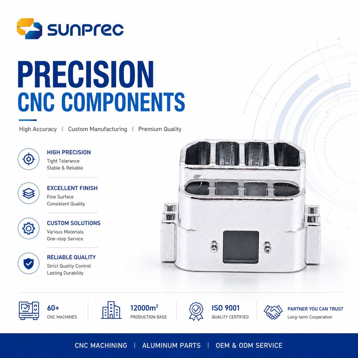
This guide is written for design engineers and sourcing teams that have already moved past the question of whether die casting is suitable, and now need to decide on alloy, wall section, tolerance strategy, secondary machining and validation. It uses the verified capability parameters of SUNPREC HARDWARE CO., LTD., a Dongguan-based metal parts manufacturer established in 2020 that supplies die casting, CNC machining and extrusion parts to EU and USA markets, with a 3,500 m² factory, 200 employees and a 10-engineer R&D team.
Problem Definition: What Makes a Wall "Thin" in Die Casting
Thin-wall die casting describes a part whose nominal wall is close to the minimum thickness a given alloy can be formed at while still filling the cavity, cooling without distortion and ejecting cleanly. The limit is material-specific, which is why the same drawing can be aggressive in aluminum and comfortable in zinc.
- Zinc alloy (Zamak 3 / Zamak 5): minimum wall thickness 0.4 mm, produced on a hot-chamber process.
- Aluminum alloy (ADC12 / A380): minimum wall thickness 0.8 mm, produced on a cold-chamber process.
- Dimensional tolerance: ±0.01 mm for die casting parts in this range.
- One-step integrated forming: complex thin-wall parts are formed in a single step, giving higher overall rigidity without splicing gaps and good shock resistance.
- Secondary operation: parts are compatible with secondary 3-axis CNC milling for precise holes, grooves and fitting surfaces.
Three engineering problems appear when a wall is pushed toward that floor. The first is fill: a thin, long section cools faster than metal can travel through it, so features far from the gate are the first to show incomplete filling. The second is dimensional stability: thin sections cool faster than thick ones, and uneven contraction shows up as distortion or as a dimension that moves outside the ±0.01 mm band. The third is load path: a thin wall carries less section, so the safety factor applied to a load-bearing area becomes the deciding variable rather than the nominal thickness on the drawing.
The design response is not to thicken everything. It is to select the alloy whose minimum wall matches the intended section, apply the correct safety factor to load-bearing sections, and route features that need tighter geometry to secondary machining rather than forcing them into the casting tool.
Industry Background: Why Thin Walls Are Being Specified More Often
Die casting is a mature, high-volume process, and the direction of demand is toward thinner, more integrated parts. The global die casting market was valued at USD 93.56 billion in 2025 (Fortune Business Insights). Aluminum dominates the material mix: aluminum die casting held a 74.78% share of the global die casting market by raw material in 2025 (Mordor Intelligence), and the transportation segment accounted for more than 64.0% of aluminum die casting revenue in the same year (Grand View Research).
Zinc is a smaller but expanding part of the picture. Zinc die casting has been identified as a fast-growing segment on the basis of cost-effectiveness and EMI shielding properties in consumer electronics (Market Research Future). Magnesium follows a similar growth pattern at a smaller scale: the global magnesium casting market was valued at USD 1.42 billion in 2026 and is projected to reach USD 2.96 billion by 2035, a CAGR of 8.9% (Business Research Insights).
Two structural drivers sit behind those figures. First, enclosures that once consisted of a frame plus panels plus fasteners are now specified as a single formed part, because integration removes assembly steps and joint-related failure modes. Second, thermal and weight targets in electronics, instrumentation and mobility applications push housings toward thinner sections, where a heat sink and a structural housing can be the same component. Both drivers land directly on the wall thickness decision, which is why minimum wall data for each alloy matters more in a quotation review than it did when parts were thicker and more forgiving.
Compliance context matters as well. For die casting suppliers serving the automotive industry, IATF 16949:2016 is the mandatory quality management system standard (Bian Diecast). Buyers working on automotive programs should confirm the applicable standard with the supplier early, and request the corresponding quality documentation before tooling is released. For non-automotive thin-wall parts such as instrument housings or equipment enclosures, the governing requirements come from the buyer's drawing and the end market rather than from IATF.
Detailed Solution: Alloy and Wall Thickness Selection at 0.4 mm and 0.8 mm
Alloy selection for a thin-wall part is a three-way trade between fill capability, mechanical strength and functional requirement. The parameters below define the envelope.
Zinc alloy thin-wall parts — 0.4 mm minimum wall
- Minimum wall thickness: 0.4 mm.
- Typical alloys: Zamak 3 and Zamak 5.
- Tensile strength range: 40–80 MPa.
- Process route: hot-chamber zinc alloy casting, with a design safety factor of 1.3–1.5.
- Functional advantage: zinc and magnesium alloys have good vibration damping, which suits precision instruments and power tools.
Zinc is usually the correct choice when the wall is genuinely thin, when the part is small and detailed, and when vibration has to be managed rather than tolerated. Precision instrument housings, power tool components and small electronic enclosures are typical fits. The trade-off is mechanical: the 40–80 MPa tensile range sits below aluminum, so a zinc wall carries less load for the same section.
Aluminum alloy thin-wall parts — 0.8 mm minimum wall
- Minimum wall thickness: 0.8 mm.
- Typical alloys: ADC12 and A380.
- Tensile strength range: 80–120 MPa.
- Process route: cold-chamber aluminum alloy casting, with a design safety factor of 1.2.
- Functional advantages: excellent heat dissipation and lightweight construction; aluminum alloy supports colorful anodizing, powder coating and painting.
Aluminum is the default when the part has to combine structure, thermal performance and low weight. Heat sink die casting parts, equipment housing die casting parts, motor housing die casting parts and structural die casting parts all sit in this group, as do automotive die casting parts. The trade-off is the wall floor: 0.8 mm is roughly double the zinc minimum, so a project that needs both a zinc-thin wall and aluminum-level tensile strength cannot be satisfied by alloy choice alone — it has to be resolved through geometry.
Magnesium alloy parts
Magnesium alloy die casting components are part of the same production range and share the vibration-damping advantage noted for zinc, which makes them relevant for precision instruments and power tools. Where magnesium is selected, the wall and tolerance parameters should be confirmed against the drawing rather than assumed from the zinc or aluminum figures.
Reading the strength and safety factor numbers together
The aluminum tensile range of 80–120 MPa sits above the zinc range of 40–80 MPa, while zinc offers the thinner wall floor and the higher safety factor band. The safety factor is not decoration: for cold-chamber aluminum alloy parts the design safety factor is 1.2, and for hot-chamber zinc alloy parts it is 1.3–1.5. In practice this factor sets how much section margin is kept above the calculated load, so the thinner the nominal wall, the more the factor drives the final thickness. A designer who reduces a wall for weight without re-checking the factor is removing margin rather than material.
Detailed Solution: Tolerance Strategy at ±0.01 mm
A dimensional tolerance of ±0.01 mm is the tolerance band carried by die casting parts in this range, and it is what converts a thin-wall casting from an appearance part into a functional one. The value applies to the dimensions defined on the drawing, so the practical design task is deciding which dimensions deserve that band and which do not — applying a tight tolerance to every feature raises cost without improving function.
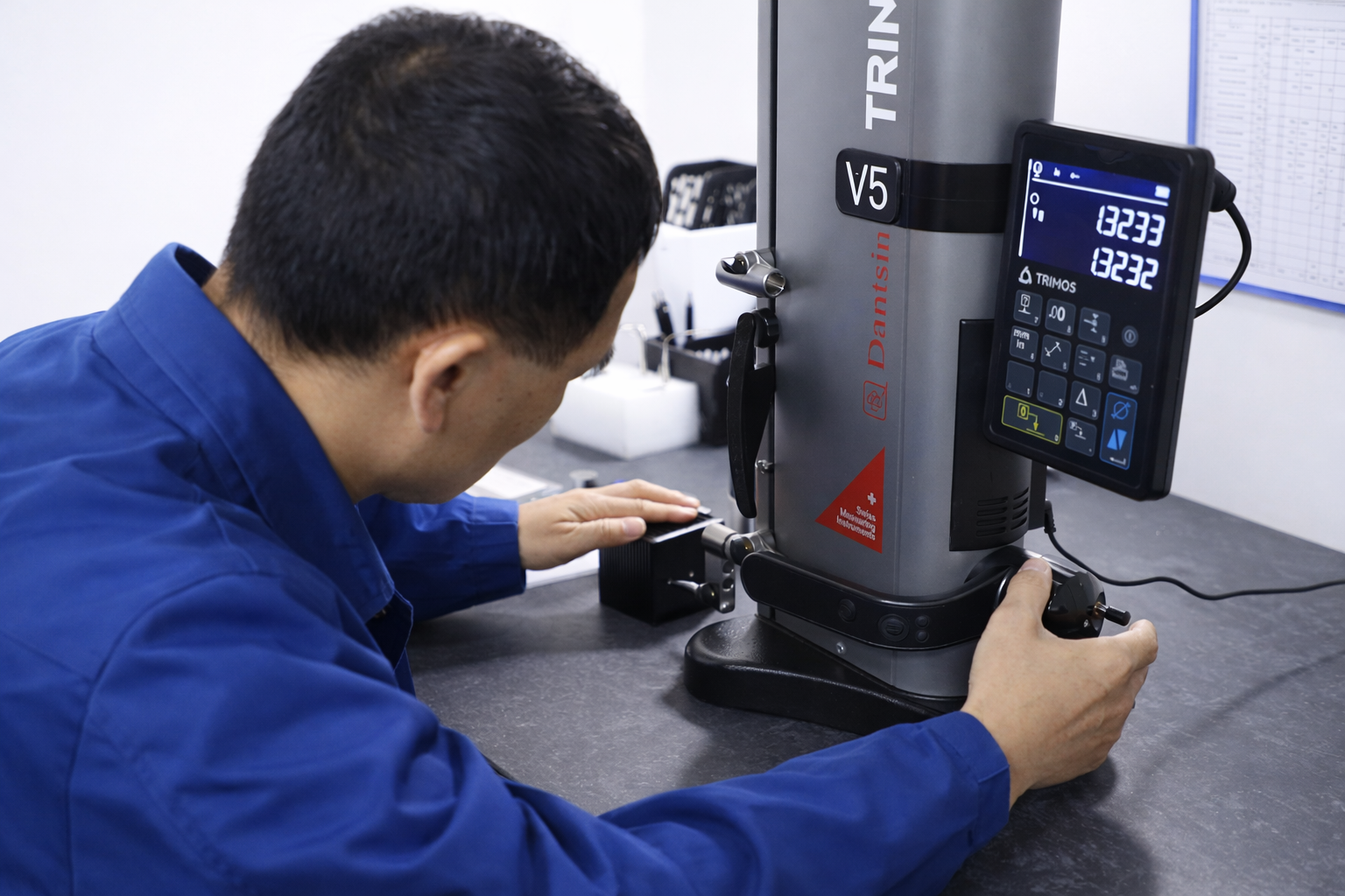
Capability behind the tolerance is supported by the measurement chain, not by the casting tool alone. Final inspection uses calipers, micrometers, a height gauge and a surface roughness tester, and critical components are verified on a coordinate-measuring machine (CMM) for tight-tolerance requirements. At the machining level, the majority of the CNC machining centers are FANUC machines with a machine tolerance of 0.005 mm, and metrology equipment includes a HEXAGON system, a 2.5D projector and a TRIMOS height gauge.
Design rule of thumb: define the ±0.01 mm band on the dimensions that control fit and function — bore positions, mating faces, groove widths — and let non-critical dimensions carry looser, cost-efficient tolerances. A casting tool is not the right place to chase a tight dimension that a secondary machining pass can hold more reliably.
One-Step Integrated Forming vs Multi-Part Assembly
Complex thin-wall parts in this range are produced by one-step integrated forming, which means the housing, ribs, bosses and mounting features are formed together rather than joined afterwards. The consequence for the buyer is higher overall rigidity without splicing gaps, plus good shock resistance.
Integrated forming removes several categories of cost and risk that are easy to underestimate during the research stage. Assembly tolerances no longer stack, because there is no joint to accumulate error across; fasteners and the labour to install them disappear; and the joint itself — often the weakest point of a housing under vibration or impact — no longer exists. Integration also makes the ±0.01 mm tolerance more useful, because a tight dimension on a single formed part is more meaningful than a tight dimension on a bracket that is bolted to a panel.
The limit is tooling complexity. The more function that is integrated into one thin-wall part, the more the die has to do in one shot, so the geometry should be planned as a system rather than feature by feature.
Secondary 3-Axis CNC Milling: Precise Holes, Grooves and Fitting Surfaces
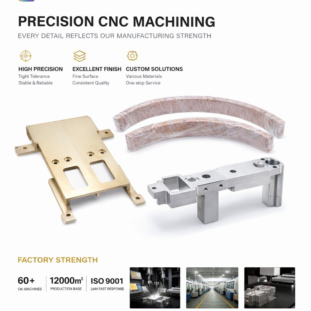
Die casting parts in this range are compatible with secondary 3-axis CNC milling for precise holes, grooves and fitting surfaces. This is the layer of the process that resolves the conflict between casting economics and functional geometry: the casting forms the body, the ribs and the thin walls, and milling cuts the features that need a machined surface or a position that the die cannot deliver directly.
The machining itself is run under controlled parameters. Cutting conditions — spindle speed, feed rate and depth of cut — are controlled, and continuous flood coolant reduces cutting heat, extends tool life and produces a smooth surface finish. Workpieces are firmly clamped to minimize vibration and keep the operation stable, and the work is carried out in a clean, temperature-controlled workshop environment.
Process monitoring is continuous rather than end-of-line only. Technicians monitor spindle load, vibration and dimensional stability throughout the entire cutting process, and real-time inspection is carried out during production to keep tight tolerances. The requirement driving this level of control is micron-grade precision tolerance control combined with the realization of complex 3D contour machining — which is the same requirement that supports the ±0.01 mm band on the finished thin-wall part. Where the geometry demands it, 3-axis, 4-axis and 5-axis CNC machining options are available, and parts can be produced according to customer 2D/3D drawings or samples.
Step-by-Step Breakdown: Designing and Validating a Thin-Wall Part
The sequence below reflects how a thin-wall project should be worked through from specification to serial delivery. Each step exists to protect the two limiting numbers: the minimum wall for the alloy and the ±0.01 mm tolerance band.
- Define the function and the load path. Establish which sections carry load, which carry vibration and which are purely enclosure. Load-bearing sections are where the safety factor applies: 1.2 for cold-chamber aluminum alloy, 1.3–1.5 for hot-chamber zinc alloy.
- Set the nominal wall from the alloy floor. Start no thinner than 0.4 mm for zinc alloy and 0.8 mm for aluminum alloy. If the target wall is below the floor for the chosen alloy, change the alloy or change the design — do not assume the process will compensate.
- Check the strength requirement against the tensile range. Aluminum alloy parts carry 80–120 MPa and zinc alloy parts 40–80 MPa. Where the calculated stress sits close to the top of the range for the selected alloy, increase section or move to aluminum.
- Decide the tolerance map. Allocate the ±0.01 mm band to fit- and function-critical dimensions and loosen the rest. Publish the tolerance callouts feature by feature rather than as a blanket note.
- Plan one-step integrated forming. Consolidate housing, ribs, bosses and mounting points into a single formed part to gain rigidity without splicing gaps and to improve shock resistance.
- Route precise features to secondary 3-axis CNC milling. Holes, grooves and fitting surfaces that exceed what the casting can produce directly are machined in a secondary operation.
- Specify surfaces early. Aluminum alloy parts support colorful anodizing, powder coating and painting; surface-plated and powder-coated die casting parts are standard finishing routes in the range. Finishing choice affects masking, datum selection and inspection sequence, so it belongs in the design review, not the packaging stage.
- Validate before scaling. First-article inspection is performed for every new batch. Final inspection uses calipers, micrometers, height gauge and a surface roughness tester, and critical components are verified on a CMM.
- Confirm commercial parameters. Production runs at a cycle time of 15–90 seconds per piece with high automation, a minimum order quantity of 10 units, a lead time of 21–30 days, and a monthly capacity of 4,200,000 units.
Use Cases: Where Thin-Wall Die Casting Fits
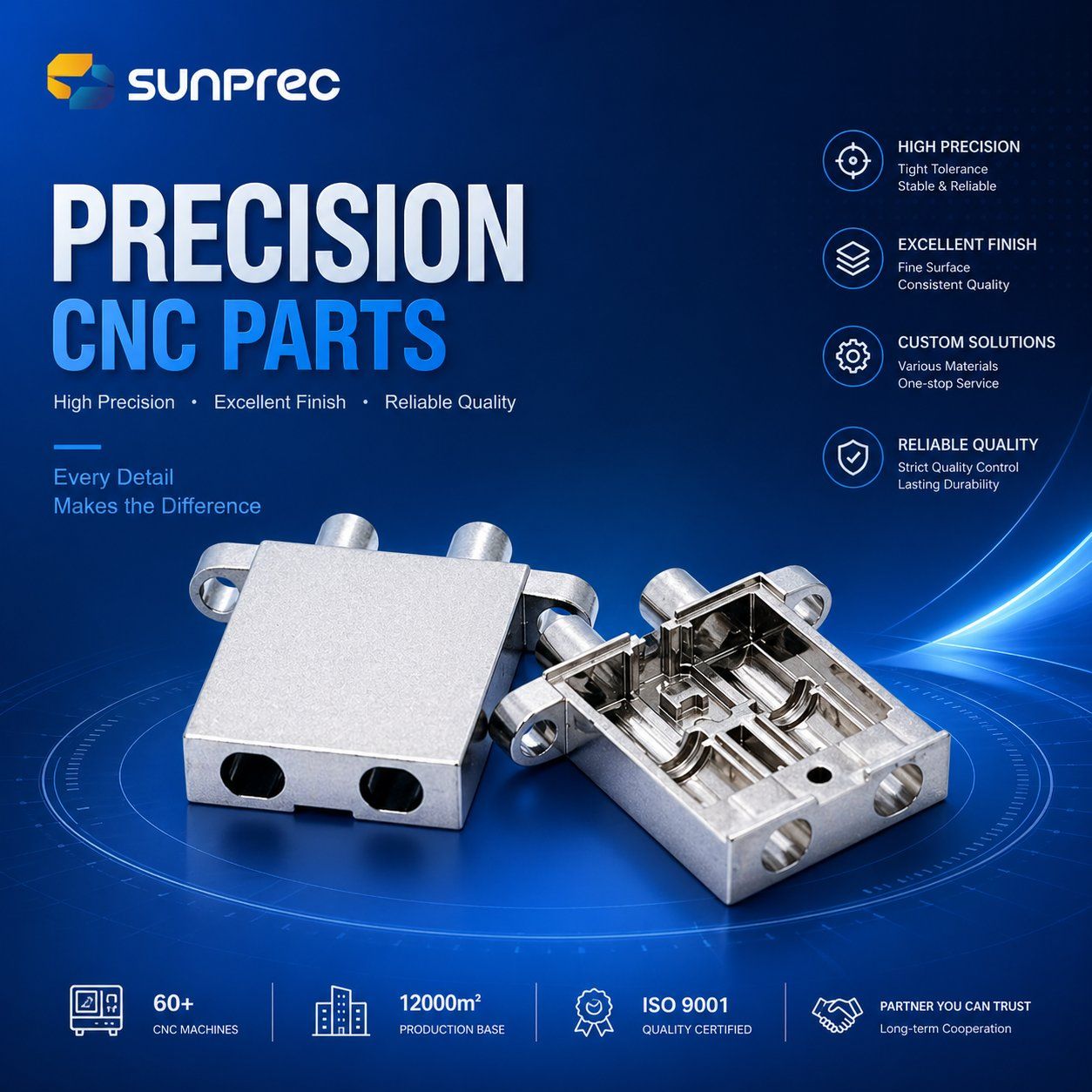
Thin-wall capability is applied across the part families in the die casting range: aluminum alloy die casting parts, magnesium alloy die casting components, zinc alloy die casting parts, heat sink die casting parts, equipment housing die casting parts, motor housing die casting parts, precision die casting parts, surface plated die casting parts, structural die casting parts and custom machined die casting parts.
Industries served include aerospace, automotive, semiconductor, medical, new energy, rail traffic, robotics and automation, and instrumentation. In these applications the thin wall is usually functioning, not cosmetic:
- Instrument housings and precision instruments: zinc and magnesium alloys bring vibration damping, which matters in measurement and power tool products.
- Heat sinks and electronic enclosures: aluminum alloy brings excellent heat dissipation with lightweight construction, allowing a housing and a thermal path to be one part.
- Motor housings and equipment housings: integrated forming delivers higher rigidity without splicing gaps and good shock resistance.
- Communication device and household appliance parts: thin-wall forming keeps enclosures slim while the ±0.01 mm band holds connector and fitting geometry.
- Structural and hardware fitting parts: the 80–120 MPa aluminum tensile range supports load-carrying sections at 0.8 mm minimum wall.
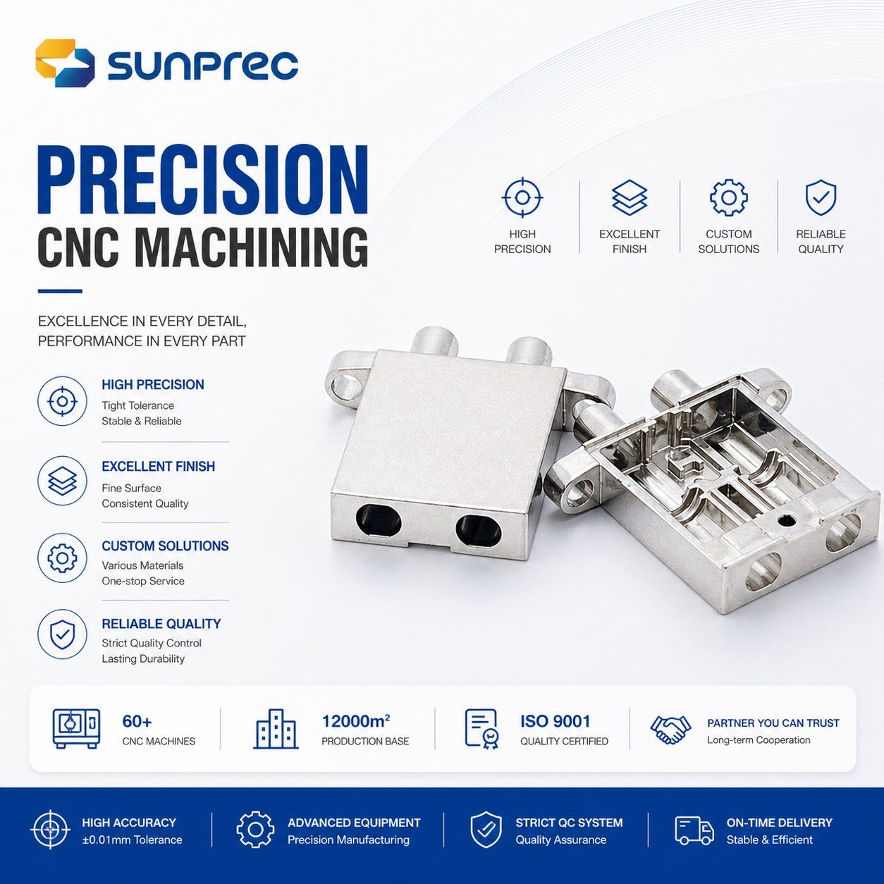
Project scale in this range is not limited to prototype volumes. Custom metal parts have been supplied at quantities such as 10,000 units per project to aerospace, automotive, medical device, new-energy equipment and industrial equipment OEMs across Australia, Germany, France, Israel, Italy, Mexico and the United States, with cooperation running for more than five years on the longest-running accounts. The supply model covers the full sequence from custom sample fabrication and small-batch trials through to continuous mass manufacturing shipments.
Comparison Table: Zinc vs Aluminum Thin-Wall Die Casting
The table below compares the two primary alloys using the verified parameters of this production range. It is a selection aid, not a ranking: the correct alloy depends on which column matches the functional requirement of the part.
| Parameter | Zinc Alloy (Hot-Chamber) | Aluminum Alloy (Cold-Chamber) |
|---|---|---|
| Minimum wall thickness | 0.4 mm | 0.8 mm |
| Typical alloys | Zamak 3, Zamak 5 | ADC12, A380 |
| Tensile strength | 40–80 MPa | 80–120 MPa |
| Design safety factor | 1.3–1.5 | 1.2 |
| Dimensional tolerance | ±0.01 mm | ±0.01 mm |
| Vibration damping | Good — selected for precision instruments and power tools (also applies to magnesium) | Selected primarily for strength, weight reduction and heat dissipation |
| Thermal and weight profile | Used where damping and detailed thin-wall geometry dominate | Excellent heat dissipation and lightweight construction |
| Surface finishing | Surface plated die casting parts are part of the range | Colorful anodizing, powder coating and painting |
| Forming approach | One-step integrated forming for complex thin-wall parts | One-step integrated forming for complex thin-wall parts |
| Secondary machining | Compatible with secondary 3-axis CNC milling | Compatible with secondary 3-axis CNC milling |
Two readings of the table are worth flagging for evaluation-stage buyers. First, the tolerance is identical for both alloys at ±0.01 mm, so tolerance is not the differentiator between zinc and aluminum — wall thickness and strength are. Second, the segment-level growth of zinc is driven by cost-effectiveness and EMI shielding in consumer electronics (Market Research Future), while aluminum's dominant 74.78% material share is anchored in transportation demand (Mordor Intelligence). Both signals point to a supply base that already runs both processes, which is why the selection should be made on part function rather than on supplier convenience.
FAQ: Thin-Wall Die Casting Design Questions
Which compliance standard applies to thin-wall die casting parts?
For die casting suppliers serving the automotive industry, IATF 16949:2016 is the mandatory quality management system standard, so automotive programs should confirm this requirement during supplier qualification. For thin-wall parts used in instrumentation, electronics or appliance applications, the governing requirements come from the buyer's drawing and the end market rather than from IATF. In every case, the evidence behind a compliance claim is inspection documentation: first-article inspection for every new batch, dimensional checks with calipers, micrometers, a height gauge and a surface roughness tester, and CMM verification for critical components.
Can ±0.01 mm tolerance be held on a thin-wall part?
Yes. Die casting parts in this range are specified to a dimensional tolerance of ±0.01 mm, and features that the casting cannot produce directly are finished by secondary 3-axis CNC milling for precise holes, grooves and fitting surfaces. Support comes from the measurement chain and the machining base: FANUC CNC machining centers with a machine tolerance of 0.005 mm, HEXAGON metrology equipment, a 2.5D projector and a TRIMOS height gauge, with micron-grade precision tolerance control and real-time inspection during production. Because a tolerance callout applies to the dimensions defined on the drawing, the band should be assigned feature by feature.
What drives the cost of a thin-wall die casting part?
Four variables dominate. The first is wall thickness relative to the alloy floor — 0.4 mm for zinc and 0.8 mm for aluminum — since sections near the limit are less forgiving of design changes. The second is the amount of secondary 3-axis CNC milling needed for precise holes, grooves and fitting surfaces. The third is surface finishing, where options such as anodizing, powder coating and painting add process steps. The fourth is volume: production runs at a cycle time of 15–90 seconds per piece with high automation, which makes the process well suited to long-term repeat monthly orders with consistent pricing.
Can a thin-wall design be validated with a sample before mass production?
Yes. OEM and ODM custom manufacturing is available, and customization options include material selection, dimensional tolerances, surface treatments, batch sizes and packaging according to customer requirements, with a minimum order quantity of 10 units. Validation follows a staged path: custom sample fabrication, then small-batch trials, then continuous mass manufacturing. First-article inspection is performed for every new batch, so the sample stage produces dimensional evidence rather than only a visual reference, and critical dimensions can be verified on a CMM.
What is the lead time and production capacity for thin-wall die casting parts?
Standard lead time is 21–30 days, with a monthly capacity of 4,200,000 units and a minimum order quantity of 10 units. Production is supported by FANUC, UL+ and HEXAGON equipment, and the company exports to EU and USA markets, with around 90% of output going to export and cooperation extending to more than 50 countries and over 300 clients. To move a thin-wall project forward, share the 2D/3D drawing or a sample along with the target wall thickness, alloy and tolerance critical dimensions, and request a quotation and sample plan through service@sunprec.com. The full capability overview is available in the SUNPREC presentation PDF.
Conclusion: Matching the Design to the Process
Thin-wall die casting is a design discipline built on known numbers. Zinc alloy forms down to 0.4 mm minimum wall with 40–80 MPa tensile strength and a design safety factor of 1.3–1.5 on the hot-chamber process. Aluminum alloy forms down to 0.8 mm with 80–120 MPa tensile strength and a safety factor of 1.2 on the cold-chamber process. Both hold a dimensional tolerance of ±0.01 mm, which lets a single integrated part replace an assembled housing, and both accept secondary 3-axis CNC milling where precise holes, grooves and fitting surfaces are required.
The evaluation-stage decision therefore comes down to three questions. Is the required wall at or above the alloy floor? Is the load within the tensile range of the selected alloy with the correct safety factor applied? And are the tight dimensions concentrated where they are worth the cost? Answering those three questions before tooling starts is what separates a thin-wall program that scales into monthly production from one that requires repeated design revisions.

Start with a drawing and a target wall thickness
SUNPREC HARDWARE CO., LTD. manufactures die casting, CNC machining and extrusion parts in Dongguan, China, with OEM and ODM custom manufacturing covering material, tolerance, surface treatment, batch size and packaging.
Send your 2D/3D drawing or sample, the planned alloy (Zamak 3/5, ADC12 or A380), the minimum wall thickness and the dimensions that require the ±0.01 mm band. Samples can be produced from a minimum order quantity of 10 units, with a standard lead time of 21–30 days.
Email: service@sunprec.com | Tel: +86-769-21686613 | Website: www.sunprec.com
Download the full capability and equipment overview: SUNPREC Presentation (PDF).
Have Questions or Need More Details?
Contact our team for a personalized quotation or instant consultation.
Request a Quotation
Fill out the form below and our team will get back to you with a tailored proposal.
WhatsApp Direct Chat
Prefer to chat in real-time? Message us on WhatsApp for instant assistance & quick answers.
- Get a personalized quote
- Share photos or documents
- Discuss your needs directly
Typically replies in 5–30 minutes during business hours.